Decoding the Current Transformer Symbol: Your Electrical Blueprint Guide

Ever wondered about those cryptic squiggles and circles on electrical diagrams? They're not just random doodles; they're a language, and one crucial symbol you'll encounter is the current transformer schematic symbol. Understanding this symbol is key to deciphering circuit designs and grasping how electrical systems monitor and manage power flow.
The current transformer symbol represents a device that measures alternating current (AC) by producing a proportional smaller current that's safer and easier to manage. Imagine trying to directly measure the massive currents flowing through high-voltage power lines – dangerous and impractical! Current transformers step down these currents to manageable levels, allowing for safe metering and protection systems.
Historically, the need for current measurement arose with the growth of AC power systems in the late 19th century. Early current measurement methods were cumbersome and risky. The development of the current transformer marked a significant advancement, enabling safe and accurate monitoring of large currents. The symbol itself has evolved over time, becoming standardized for clarity and universal understanding within the electrical engineering community.
The importance of this seemingly simple symbol cannot be overstated. It's the visual shorthand for a critical component in power systems, playing a vital role in protection, metering, and control applications. Misinterpreting or overlooking this symbol in a schematic could lead to incorrect system design and potentially hazardous situations. Therefore, mastering its interpretation is fundamental for anyone working with electrical systems.
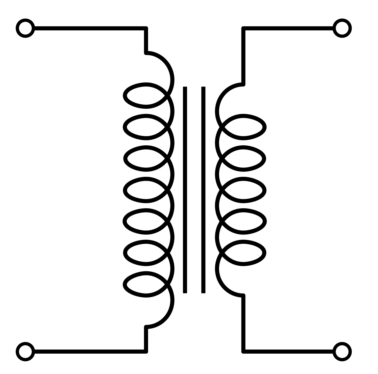
The basic current transformer symbol resembles two coils wrapped around a core. Variations exist to denote different types of CTs, like window-type or bushing-type. The primary side of the symbol represents the connection to the high-current line, while the secondary side indicates the connection to the measuring or protection circuitry. The symbol often includes markings to indicate the CT ratio, which defines the proportional relationship between primary and secondary currents. For instance, a 1000:5 CT ratio means that a 1000 Amp primary current will induce a 5 Amp secondary current.
One of the benefits of using CTs is safety. By reducing high currents to manageable levels, they allow technicians and engineers to work with electrical systems without direct exposure to dangerous voltage or current levels. Another benefit lies in their accuracy. Modern CTs offer high precision in current measurement, crucial for precise metering and billing in power distribution. Finally, their versatility allows them to be utilized in diverse applications, from simple current monitoring to sophisticated protection schemes against overcurrents and faults. For example, a CT can trigger a circuit breaker to trip if a fault current exceeds a predetermined threshold, protecting equipment and personnel.
When incorporating current transformer symbols into schematics, accuracy and clarity are paramount. Follow established standards like IEC or ANSI for consistent representation. Clearly mark the CT ratio and any other relevant information, such as polarity and accuracy class. Ensure that the symbol's placement in the schematic accurately reflects the CT's position within the physical system.
Advantages and Disadvantages of Current Transformers
| Advantages | Disadvantages |
|---|---|
| Safe current measurement | Limited DC measurement capability |
| Accurate metering | Can be affected by external magnetic fields |
| Versatile applications | Saturation at high overcurrents |
Frequently Asked Questions:
1. What is a CT ratio? - The ratio of primary to secondary current.
2. What are the different types of CTs? - Window-type, bushing-type, etc.
3. Why are CTs used in protection systems? - To detect overcurrents and faults.
4. How is the CT symbol represented in schematics? - Two coils around a core.
5. What are the applications of CTs? - Metering, protection, control.
6. What is the importance of CT polarity? - Ensures correct directional measurement of current.
7. What are some common problems with CTs? - Saturation, open circuits.
8. How to choose the right CT for an application? - Consider factors like current rating, accuracy class, and application type.
In conclusion, the current transformer schematic symbol, though seemingly small, holds immense significance in electrical engineering. It represents a vital component for safe and efficient power system operation. From protecting against overcurrents to enabling accurate metering, its role is critical. By understanding this symbol and its implications, we can unlock the secrets of complex electrical circuits and contribute to building more reliable and secure power systems. Taking the time to master the nuances of the current transformer symbol empowers us to design, analyze, and troubleshoot electrical systems effectively, ensuring safe and efficient operation for all. As technology continues to evolve, the role of accurate current measurement remains paramount, making the humble current transformer symbol an enduring icon in the world of electrical engineering. Dive deeper into the fascinating world of electrical systems and discover the power within these symbols – it's a journey well worth taking.
Elevating your space with dark grey a sherwin williams paint exploration
Unlocking magic disney drawing for kids
Unlock pinterest your easy guide to joining


