Unlocking Wiring Diagrams Relay Symbol Secrets

Ever stared at a wiring diagram like it's a cryptic treasure map? You're not alone. Those seemingly simple lines and squiggles hold the key to understanding how electrical systems work, and cracking the code of relay symbols is a crucial step in becoming a wiring whisperer. Relays, those electromechanical workhorses, are the unsung heroes of many circuits, and understanding their symbolic representation is paramount to deciphering complex electrical systems.
Imagine trying to bake a cake without knowing what the symbols in the recipe mean – flour, sugar, eggs. Chaos, right? Wiring diagrams are the recipes of the electrical world, and relay symbols are essential ingredients. They are a shorthand language that allows engineers and technicians to communicate complex designs efficiently. They depict relays in a simplified, standardized manner, conveying critical information about their function and connection within a circuit.
Relay symbols haven't always been standardized. In the early days of electrical engineering, various depictions were used, leading to confusion and misinterpretations. Over time, the need for a unified language became evident. Organizations like the International Electrotechnical Commission (IEC) and the Institute of Electrical and Electronics Engineers (IEEE) stepped in to establish common standards, streamlining the design and interpretation of wiring diagrams globally.
Why are relay symbols so important? Because they prevent costly mistakes. Misinterpreting a relay symbol can lead to faulty wiring, malfunctioning equipment, and even safety hazards. These symbols act as a universal language, allowing electricians and technicians worldwide to understand and work with diverse electrical systems without the barrier of language or regional differences.
One of the primary issues surrounding relay symbols is the potential for misinterpretation, especially with less common or outdated symbols. This is why adhering to current standards and consulting reliable resources is crucial. Moreover, understanding the different types of relays and their corresponding symbols (e.g., latching relays, time-delay relays) is vital for accurate diagram interpretation.
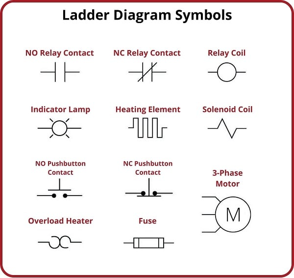
A basic relay symbol consists of a coil and a set of contacts. The coil represents the electromagnet that activates the relay, and the contacts symbolize the switches that are opened or closed by the relay's action. For instance, a normally open (NO) contact is represented by two parallel lines, indicating that the circuit is open until the relay is energized. Conversely, a normally closed (NC) contact is depicted with a diagonal line connecting the two parallel lines, showing that the circuit is closed until the relay is energized.
Three key benefits of standardized relay symbols are: Enhanced Clarity - Symbols provide a clear and concise representation of complex relay functions, reducing ambiguity. Improved Communication - Standard symbols facilitate effective communication between engineers, technicians, and other stakeholders involved in electrical projects. Reduced Errors - Standardized representation minimizes the risk of misinterpretation, leading to fewer errors during design, installation, and maintenance.
Advantages and Disadvantages of Standardized Relay Symbols
| Advantages | Disadvantages |
|---|---|
| Clear communication | Requires learning the symbols |
| Reduced errors | Potential for confusion with outdated symbols |
| International standardization | Variations can exist between standards |
Best Practices for Implementing Relay Symbols
1. Adhere to recognized standards (IEC, IEEE). 2. Use clear and concise labels. 3. Provide a legend explaining all symbols used. 4. Maintain consistency throughout the diagram. 5. Ensure adequate spacing between symbols for readability.
Frequently Asked Questions
1. What does a coil symbol represent in a relay? (An electromagnet) 2. What is the difference between NO and NC contacts? (NO closes when energized, NC opens) 3. Why are standardized symbols important? (For clear communication) 4. Where can I find resources for relay symbols? (IEC, IEEE websites) 5. What are some common types of relay symbols? (Latching, time-delay, etc.) 6. How do I interpret complex relay circuits? (Break down into smaller sections) 7. What are some common mistakes when interpreting relay symbols? (Confusing NO and NC) 8. How can I improve my understanding of relay symbols? (Practice and study resources)
Mastering relay symbols empowers you to confidently navigate the intricate world of wiring diagrams. These standardized symbols are not just arbitrary squiggles; they are essential tools for effective communication and error prevention in electrical design. By understanding their history, significance, and practical applications, you unlock the secrets of electrical systems and pave the way for efficient and reliable circuit design. So, dive in, explore the world of relay symbols, and transform those cryptic diagrams into clear blueprints for electrical success. Embrace the power of these symbols, and watch your electrical projects come to life with confidence and precision. By understanding relay symbols, you not only unlock the ability to read wiring diagrams but also contribute to safer, more efficient, and reliable electrical systems.
Finding peace in the city brisbane noise regulations
Unlocking the potential exploring rav4 hybrid models and their diverse applications
California drivers permit exam in korean


